Water Tank Design, Construction, and Installation
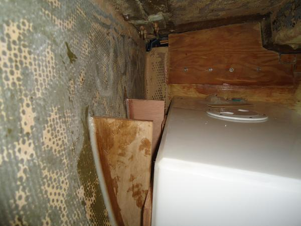
Water tanks are an important part of the restoration and modification to the Far Reach. With our boat being rebuilt around the needs of four people--two adults and two children--water capacity is important. My plan was to get as close as possible to 140 gallons total capacity. The original tanks were fine except for one major issue; they took far too much of the storage space. Originally, Far Reach had a water capacity of about 120 Gallons--not bad really considering most boats this size have less than 100 gallons. There was a 25 gallon tank under the V-berth, a 30 gallon tank under each of the settees and a 30-35 gallon tank under the quarter berth. However, with a 30 gallon tank under each settee there was practically no room left for storage. I wanted those settees open for storage of food and other supplies. The new settee design will have tremendous capacity and be very convenient to access--if I eliminated the tanks. Those two tanks had to go and since I had removed the fuel tank that had been in the bilge under the main saloon cabin sole I knew that was the perfect place for the new tanks. In my mind, that is the best place for water tanks--on the center-line and in the middle of the boat. As the water is used up and the tanks become lighter there is less affect on the trim of the boat, when they are located in the bilge, than if they are located any other place in the boat.
The tank design needed to take maximum advantage of the space in the bilge. In other words, the tanks needed to conform as much as possible to the shape of the space in the bilge--narrow at the bottom and wider at the top. The current plan for water tankage is three tanks on the centerline with a capacity of about 70-75 gallons. We will keep the 30 gallon quarter berth tank. We will built a new tank under the V berth at about 30 gallons which will get us to about 130 gallons. I researched various tank materials. SS was high on my list. SS tanks are strong and there are no lack of facilities that can repair them. But, the more I read about them and the more sailors I talked to that had experience with SS tanks the less confidence I had in my ability to get tanks that would be reliable and at a cost I could afford. Crevice corrosion plagues SS water tanks. I heard of tanks lasting 20 years. But I also heard about many tanks that had a far shorter lifespan . . . some less than three years due to massive pinhole leaks along the welds. If the design allowed them to be square or rectangle then the cost would not be out of range but as soon as I got into custom complex design the cost went up very quickly. I drew up the design and faxed it to a number of SS tank builders. The number one metal for water tanks is monel. The estimate for monel tanks were $4500! Way to high. SS 316L was next on the list but the cost ran to about $2500-$3000. 304L from $1800-$2500. This was more than I was prepared to spend--plus there remained the issue about getting tanks that would last.
I tried finding prebuilt roto-molded tanks. These were not my preference because they don't have full baffles and they can't really be repaired. But they are the least expensive and can be pretty reliable. I thought they would be a good choice if I could find ones that would closely conform to the bilge area. I contacted Kracor who at one time made bilge tanks to fit the Cape Dory 36. But, they destroyed the mold in 2003 and wanted $3000 to build a new mold. I contacted RONCO tanks in SOCAL but they did not have tanks that would fit my bilge. I took a hard look at building epoxy tanks. This seemed like a good option. It was not too expensive and I had the skills. I found an epoxy approved by the FDA for potable water tanks . . . but it was a big undertaking and I already had a full plate. Then I heard about custom welded plastic tanks. They are FDA approved. They can be built to fit any space and can have full baffles built in. Unlike roto-molded tanks these can be built very thick and can be repaired, though not in as many places as SS. I faxed the design out to three companies and got references and called them. I decided to go with Dura-Weld tanks. They have a great reputation and were easy to work with.
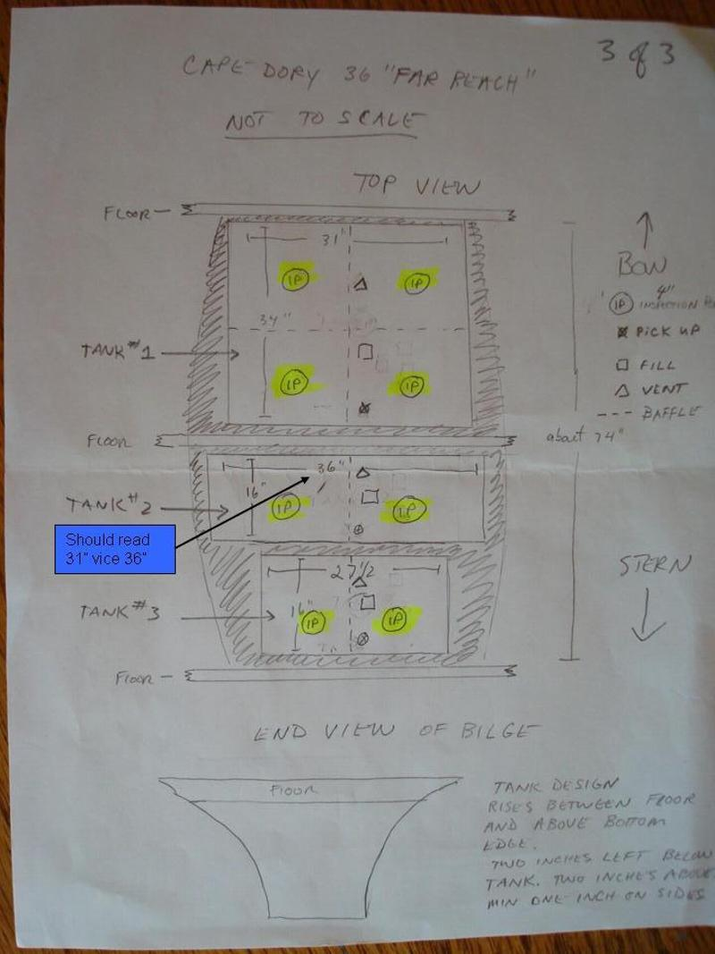
Overhead View
Side View
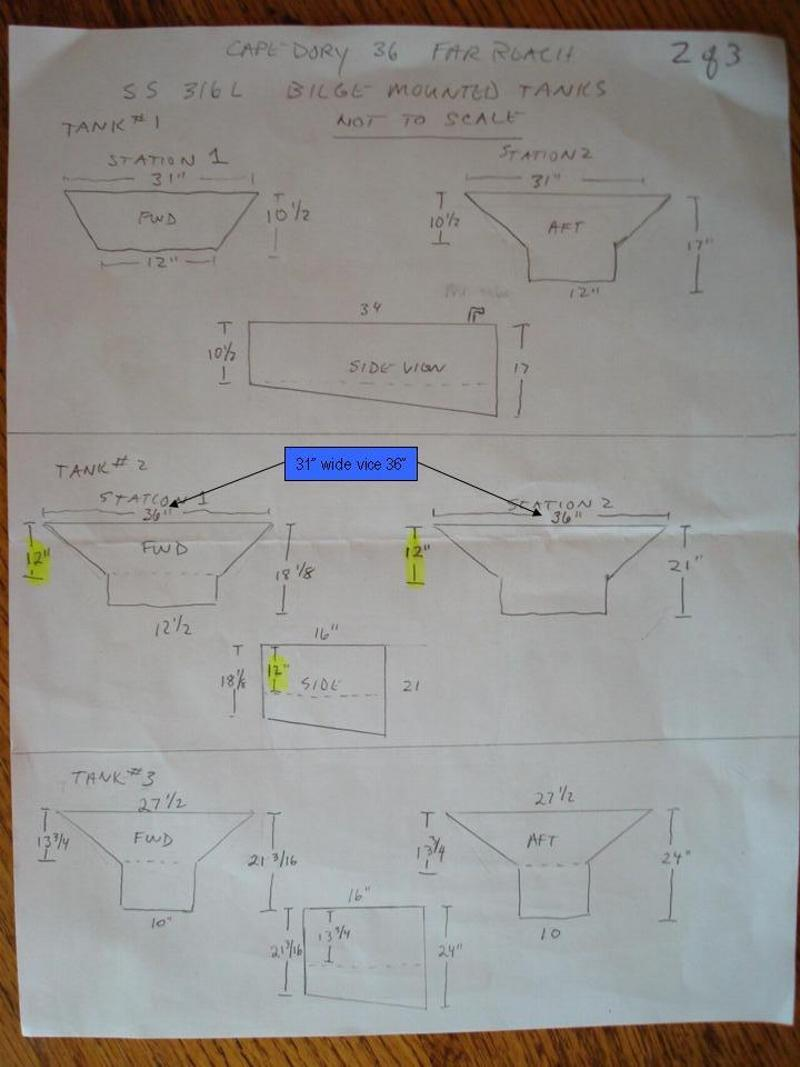
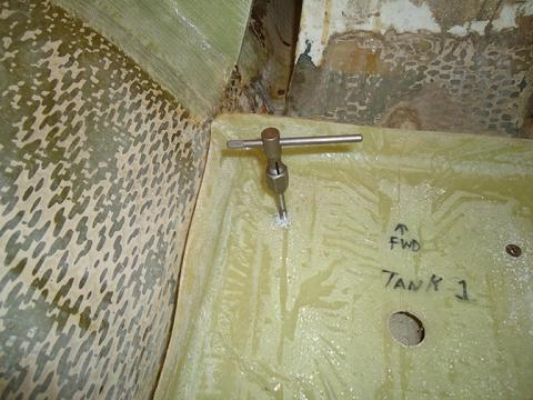
To the left are the drawings for the water tanks. The forward tank (tank #1) is 34 inches long and 31 inches wide. One baffle runs fore-and-aft and the other runs across the tank giving four compartments. Every compartment has an inspection port (IP). I had to divide the other tank into two smaller tanks or else they would not fit through the companionway. It wasn't the length of the tank that would have been the issue but the depth. The middle tanks is also 31" wide vice 36" as indicatedin the drawing. The aft tank is a bit narrower as the bilge gets narrow as it runs aft. I wanted the fill tubes all in a line from tank to tank so that access would be easier. There will be no deck fills. I'll fill the tanks by leading a hose directly into the tanks. I carefully measured the bilge area and then built cardboard mock-ups to make sure the tanks would fit.
After revising the drawings I faxed them out for quotes. After selecting Dura-Weld to build the tanks I called them and spent some time discussing the tanks with Garreth. We talked though the design and made sure we were both on the same sheet of music. It only took them about two weeks to build the tanks.
After revising the drawings I faxed them out for quotes. After selecting Dura-Weld to build the tanks I called them and spent some time discussing the tanks with Garreth. We talked though the design and made sure we were both on the same sheet of music. It only took them about two weeks to build the tanks.
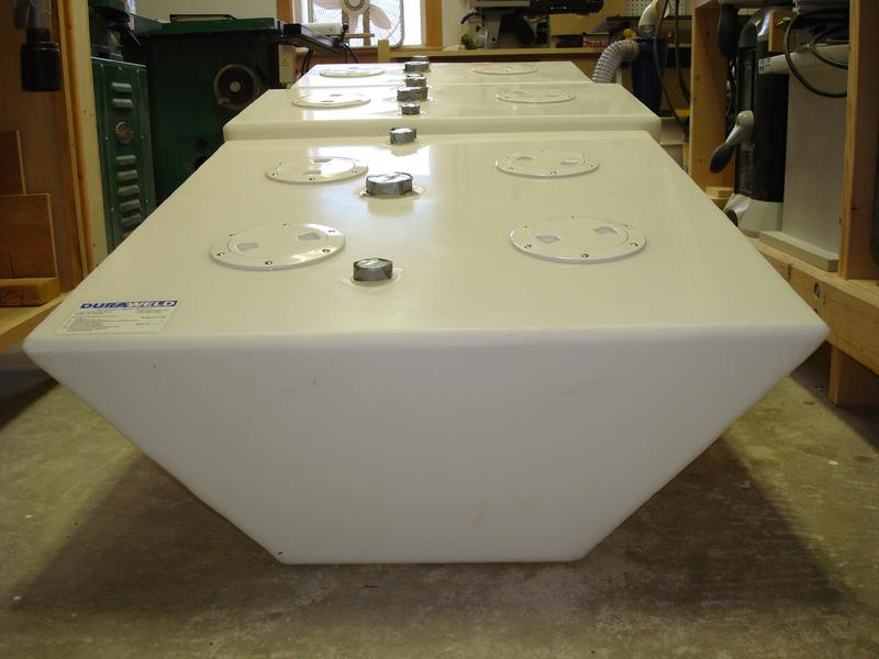
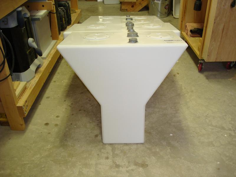
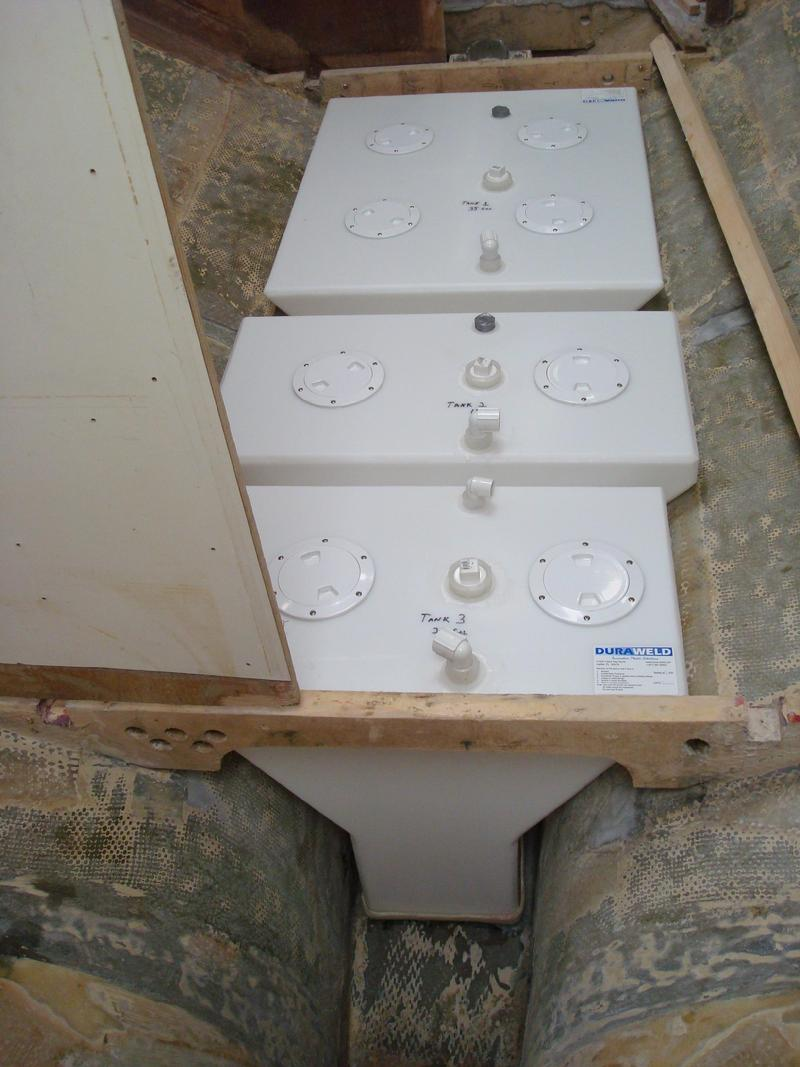
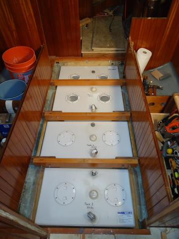
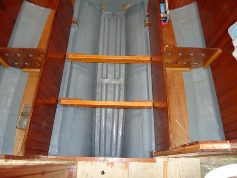
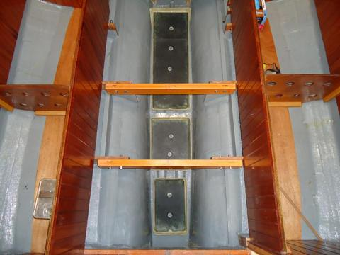
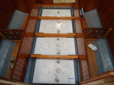
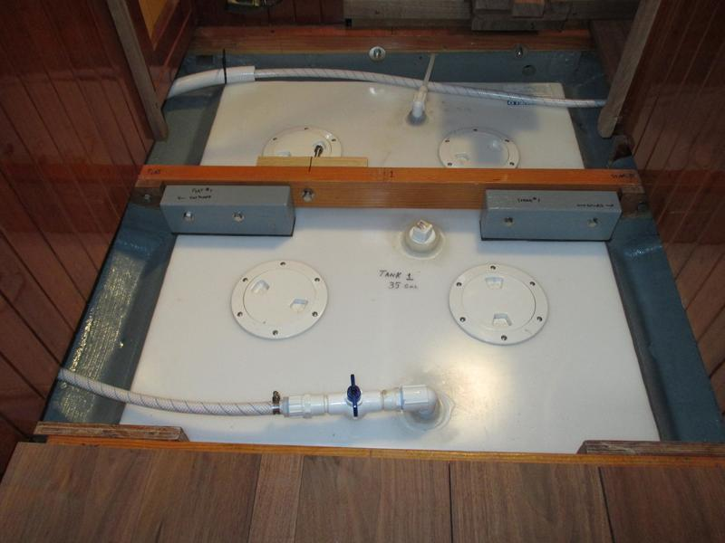
These are the water tanks. I think they look great. Dura-Weld did a great job. Compare these photos with the drawing above. The top picture is looking from what will be the forward end (shallow end of the bilge) of the tanks to the aft end (deep end of the bilge). The "down angle" of the tanks reflects the bilge sloping down as it runs aft. I am not sure of the capacity but I think somewhere between 60 and 80 gallons. When the weather warms up I'll fill the tanks with water to determine their capacity. There are three tanks. The forward tank is about 34" long and the aft tanks are each 16" long. The tanks are made from polypropylene and were nitrogen welded. They are FDA approved for potable water and are supposed to impart no taste to the water. They are supposed to be very strong (3/8" thick). Each baffled compartment has an inspection cover.
I'll build shallow fiberglass trays, molded to fit each tank bottom. I'll fastened the trays to fiberglass runners that I'll glass into the bilge. The trays will keep the bottom of the tanks from moving around. I'll use blocks on the top end of the tanks and SS straps to hold them in place.
I'll build shallow fiberglass trays, molded to fit each tank bottom. I'll fastened the trays to fiberglass runners that I'll glass into the bilge. The trays will keep the bottom of the tanks from moving around. I'll use blocks on the top end of the tanks and SS straps to hold them in place.
Looking from front to rear
Looking from rear to front
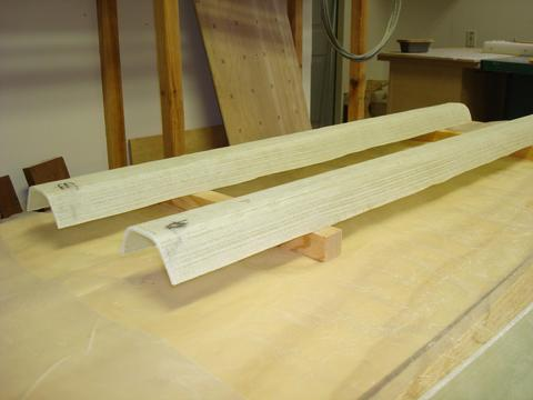
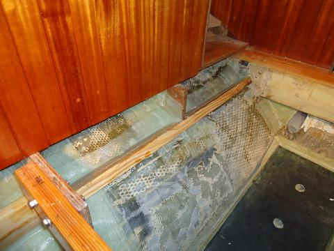
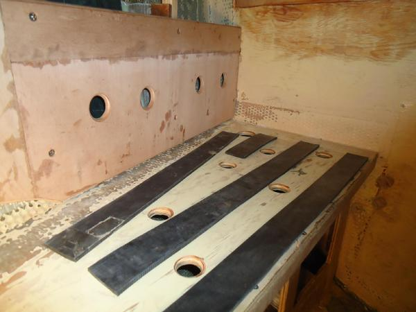
I wanted the tanks to sit in the bilge but not on the bilge floor. I wanted any water that got into the forward area of the boat to have a clear unobstructed path to the sump area. After considering many different options I decided to fabricate runners (or stringers) out of epoxy (bottom left picture). I would glass them into the bilge. I built the plug for the runners from 2X4s I bought at Lowes. I cut them to length (74") and ripped 30 degree angles on each side and made them just wide enough that 4" wide biaxial tape would just fit side to side. I think they are 1 ¼" on the two sides and 1 1/2" across the top edge. I started to sand them thinking I would wax them and then glass directly to the wood plug. However, I decided that covering them with "painters plastic" would be a lot easier. I laid three layers of 17oz biaxial tape wetted out with West System Epoxy over the plugs. After I removed them cured epoxy from the plugs I cut them to length. The front runners support the longer forward tank and the other half supports both the aft two tanks.
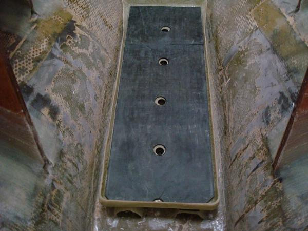
The middle picture depicts the trays I built for each tank. They were simple to build. I turned the tanks upside down. I covered them with plastic sheeting and laid four layers of 17oz biaxial cloth wetted out with West System Epoxy over the tank bottom. The next day I removed the cured trays from the tanks and trimmed them down with a grinder.
The bottom right picture shows how it will look in the boat. The forward tank is sitting in its custom molded tray. The tray will be secured to the runners with mechanical fasteners so I can remove the trays for cleaning, etc. The runners will be glassed into the bilge. All three tanks will be lined up and spaced to allow the floor timbers to fit between them. I will drill 3/8" holes in the lower aft corners of each tray to allow any water that gets into the trays to drip out into the bilge.
The runners will be glassed into the floor of the bilge.
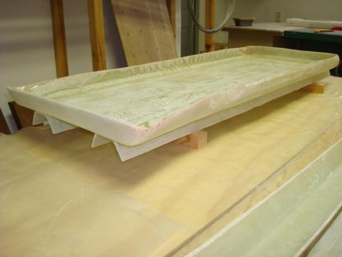
Each tank has a custom molded tray that will be secured to the runners.
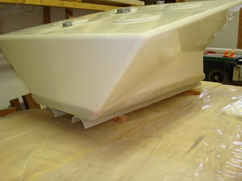
This is the forward tanks being test fitted to its tray and sitting on the runners.
Today, I epoxied the stringers in place in the bilge. First, I laid down a wetted out 1" wide piece of 17.7oz biaxial that each edge of the stringer would sit on (this was just to provide some more cloth between the polyester glass over the lead ballast and the edge of the epoxy stringer). Then I placed each edge of the stringers on the wetted tape and then filleted each side of the four stringers with 406 thickened epoxy. When it had kicked sufficiently, I laid down a 3" wide strip of 17.7oz biaxial to each side of the stringers. Tomorrow I will attach the trays to the stringers. I will use self tapping screws to fasten the trays to the stringers. That way I can remove the tanks and trays when I want to wash the boat out. The design of the stringers holds the tanks 1.5" above the bottom of the bilge and allows any water that gets into the boat to run under the stringers to the sump. The tanks will eventually be held in place with wedges and straps so they can't move around.
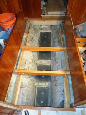
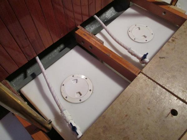
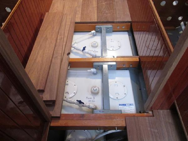
The bottom two pictures to the right are photos I took this winter and they show how the whole thing fits together. The forward tank is the closest to the front. The tanks get deeper as they go aft because the bilge slopes down and back. The aft two tanks were divided otherwise they would not have fit through the companionway hatch. Each tanks has baffles and an inspection/clean-out port for every baffled compartment.
Today, I also filled the tanks with water to see how much each tank would hold. The forward tank holds 35 gallons, the middle tanks holds 18 gallons, and the aft tank holds 20 gallons. With the 30 gallon quarter berth tank that gives me just over 100 gallons. I'll add another 25 -30 gallon tank at some point.
Stringers for the water tanks.

Each tanks sits on a custom molded epoxy tray and the tray sits on the stringers.

Three tanks for a total of 73 gallons.
There are things you will never know about your boat until you rip it apart and rebuild it. I have learned many things about the Far Reach during this project. Today I learned there are few, if any, horizontal surfaces that are level with each other anywhere on the boat.
Today, for example, I installed the water tanks. All went well. After I sat them in the trays I installed yesterday, I checked that there were level both athwartship and fore and aft. I removed them from the trays then I used #8 SS self-tapping screws to secure the trays to the stringers--they are temporary screws as they were the shortest ones I had on hand. After I reinstalled the tanks I sat back to admire them. I was thinking how much more proper they look in a boat than on a garage shelf. Then I noticed they were not level with the forward floor timber. Hmmmm. So I checked the tanks with the level. Dead on. Then I check the floor timber . . . high on the right and not just a little. I check it against the other floor timbers. They were also high on the starboard ends. I check the cockpit-- dead level. I check the cleats the supported the settees "back in the day." Level. Very interesting. Either the deck is on crooked or the boat was not level when the builder installed the floors. I will investigate this more tomorrow.
For more on floor beams go to Rebuilding the Interior.
Before I can install the floor beams in the saloon area I needed to reinstall the water tanks. The bottom of the trays are a little rough and I have been concerned that with the boat bouncing around in seaway there could be some abrasion to the tanks. So, a few days ago I ordered some 24" X 12" X 1/8" thick EPDM rubber from McMaster-Carr. This will put a thin layer of rubber between the polyethylene tanks and the epoxy trays. I trimmed the rubber with a box cutter and cut it to fit in the bottom of the trays. Once I was satisfied with the fit I cut holes in the rubber with a 1 1/2" hole saw to match the holes in the trays that are intended to allow any water that gets into the trays to drain out. The tanks fit snug in the trays so I think this was a good move.
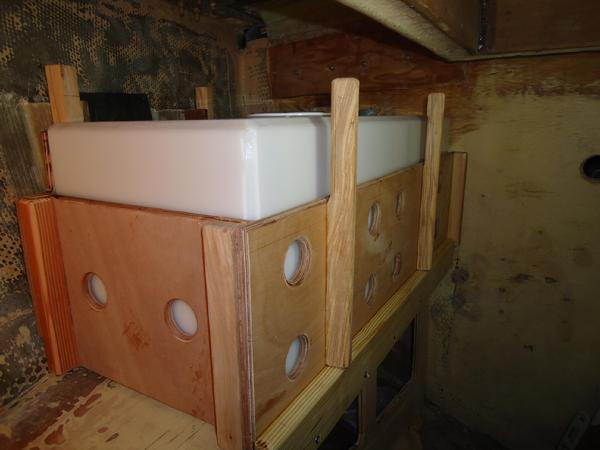
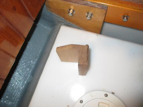
It was time to install the supports for the top of the water tanks. I built the trays they sit on two years ago. For more on that project click here. One of the challenges with plastic tanks is securing them in place. They don't have flanges on them to bolt to cross beams like SS tanks do. Many sailors foam them in place but I did not want to do that because the foam would slowly absorb water and mildew would result. So, I called Dura Weld and discussed my plan with Gareth, who built my tanks. He liked the plan. So, I spent the next couple of day installing the supports. I started by building doorskin templates between the hull and the upper edge of the tanks. Then, I traced the pattern on some Doug Fir. It took a while but I slowly shaped the fir to fit between the hull and the tanks. Once I was satisfied, and after installing and removing them several times--which by the way made me wish I had bought SS tanks--I was ready to epoxy the supports in place. I could not take the tanks out of the boat to do the work as the tanks ensured the supports were in the right place. So, when I was ready I "spot welded" the supports in place with a little thickened epoxy. Then, once the epoxy cured I removed the tanks, Next, I completed filleted the supports in place being careful not to cover the holes I cut in the support to serve as limber holes. Once the full fillets were pretty tacky I applied a single layer of biaxial to the outboard side of all the supports and to the inside for the supports that hold the center tank. The center tank has square outside edges and so the supports are vertical. They needed the extra layer of biaxial on the inside to make sure they could not move. After everything was cured I washed the amine blush off and sanded the epoxy tape and fillets. After they fully cure (about two weeks) we will paint the bilge and the supports with Interlux Grey Bilge-Kote. I still need to install the hold down blocks but that should be a simple project. One of the nice things about these supports is that it will be much harder from something dropped, like sockets, to get past the supports and under the tanks. Not impossible mind you but much less likely.
Below:
1. The tanks before the upper supports were installed.
2. The supports "spot welded" in place with thickened epoxy.
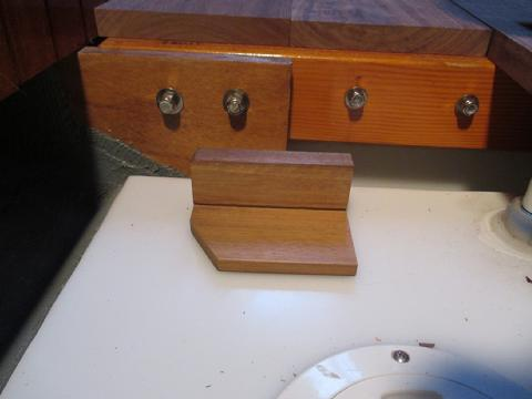
3. Biaxial added to the top side of the supports that are angled. There is a layer to both sides of the middle tank. I rabetted the inside edge of the center support so the biaxial would not come into contact with the plastic tank.
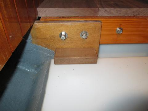
4. All the supports epoxied and taped in place.
5. Tanks reinstalled.
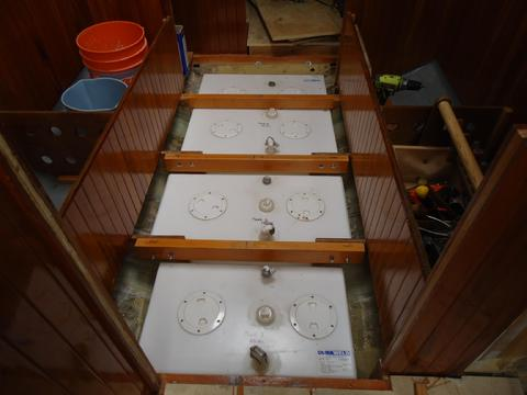
I tapped holes for machine screws to secure the water tank trays that were previously secured with self tapping screws. I as never happy with the self tapping screws. They did not provide the strength I desired. I initially planned on multiple coats of Interlux Bilge Kote to protect the fiberglass and make it easier to clean. However, the Interlux rep told me that if there was no opacity and no loss of gloss one coat was fine. All the surfaces were previously sanded. After tapping the holes and test fitting the trays, I wiped all the surfaces down with Interlux 202. This was miserable work. it was over 100 F in the boat and I had to wear a full respirator. All the inside fiberglass surfaces had to be wiped down and not just the bilge. The next day I tapped off key surfaces and the applied the paint. Fortunately, one coat did the job and saved me a lot of work. I was very satisfied with how this project turned out.
Below:
1. I tapped holes for the trays. I tapped into the runners I installed last year that support the trays about 1 3/4" above the bilge.
2. I applied one coat of Interlux BilgeKote paint.
3. Next, I reinstalled the trays and rubber mats. The tapped holes for the 1/4" flat head machine screws worked great.
4. The water tanks and cabin sole beams reinstalled.
Shower Water Tank
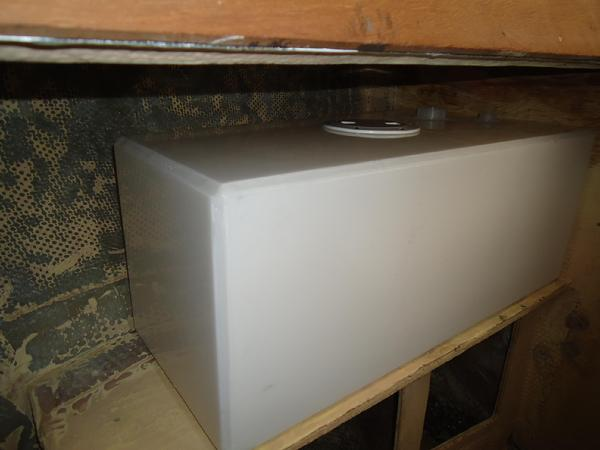
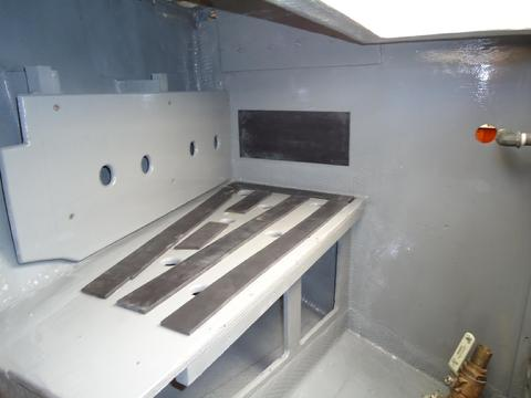
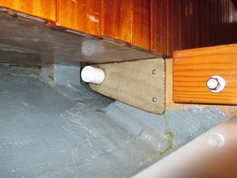
As previously mentioned, I am installing a plastic welded water tank (made by Gareth at Dura Weld) as a dedicated tank for the sitz shower tub. It will be positioned on a shelf in the portside cockpit locker as reflected in the photo to the right. I build the template from cardboard, drew it out on paper and emailed it as a PDF document to Duraweld. In no time, I had a custom tank or about half the price of SS. Dura Weld also built the rest of the water tanks. I will need to build a supporting box to keep it secure. It is a gravity feed tank that I will plumb directly to the head compartment. A ball valve will allow us to fill a dedicated pump up spray bottle (an insecticide spray bottle), with it's own storage compartment, to be used as a shower. Hot water can be added from a tea pot to make a hot shower. Simple but effective.
While waiting for the varnish to dry on the icebox I needed to have another project going. So, I decided to complete the retrofit of the port cockpit locker. That project includes installing a frame for the dedicated water tank for the sitz tub. Click here for more info on the sitz tub. I was almost out of 1/2" plywood and I don't really want to buy more when I need so little. So, I pulled together all my scraps to see what I could do. I cut the panels to the largest size possible and test fit them in the locker to check the fit and to further develop how they would be secured. Then, I epoxied in some plywood wedges with thickened epoxy to support the outboard panel. Tomorrow, after the epoxy has cured, I will remove the tank and panels and tape the ply supports in place.
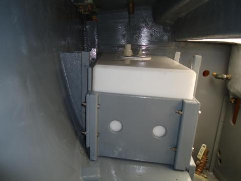
The shower water tank requires support on all four sides. I decided to raise it slightly to allow air to have access under the tank. I placed 1/4" thick rubber strips down. I drilled 1 1/2" diameter holes between the strips and routered them with a round over bit. The tall frames were positioned to allow cross beams to be through bolted over the top of the tank to keep it in the box should the boat suffer a severe knock-down. I built the box so it can be removed in order to pull the tank out of the boat if necessary. This was a time consuming job. I'll paint the locker, water tank box, and the shelving after Thanksgiving.
The rubber stirps support the bottom of the tank and allow air to circulate and water to drain out.
I test fit the box to make sure every thing fits properly. The tank will be plumbed to an on deck fill. It is the only tank so plumbed.
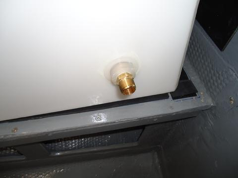
Sometimes You Have to Know When to Walk Away.For the last few days I have been painting the cockpit lockers. I can just barely fit in two of the lockers to apply the paint which requires that you pretend you are pretzel. Anyway, yesterday I was trying to complete the installation of the shower water tank which I have been working on for a while. The painting was completed. The tank was in position. All the fittings were installed except for the last one. Of course, that was the one screws into the bottom of the tank as part of the gravity feed system. To that double ended male fitting is screwed a plastic 1/2" ball valve that is threaded on after the tank is positioned on the shelf. Problem is I could not get the plastic double ended male fitting to thread into the bottom of the tank. It kept wanting to cross thread. It was late and I was tired. I had been jammed into the locker too long. I wanted this project done. I was mad. Boy was mad. But, I managed to convince myself to put down the tools and step away from the tank--"do no harm" came to mind. So, I went to the shop and listened to some music. We had a family night movie. I felt better. This morning I went back to work. I took everything apart and removed the tank up to the cockpit. The threads were boogered up just a little at the beginning of the female fitting in the bottom of the tank. There was no way to get the plastic threaded one installed. So, I went with the brass one. I applied teflon tape to the threads and stuck a 1/2" dowel rod in through the hole in the fitting so I could keep it perfectly vertical while I used a 7/8" box end wrench to carefully spin it on. I prefer to use plastic with plastic to keep the same coefficient of expansion (COE). But short of sending the tank back to DuraWeld this was the best option. Then, I went back to painting the lockers.
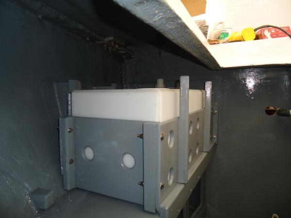
The tank is well supported and very snug in the box. Two wood "cross bars" will be secured athwart the tank connected to the uprights to hold the tank down in the box should the Far Reach suffer a severe knock-down.
Below:
1. I used Devcon "Rubber" Cement to secure the 1/4" thick rubber strips to the plywood.
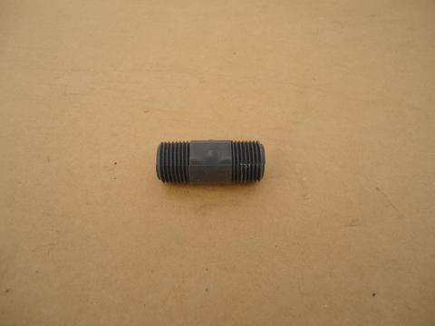
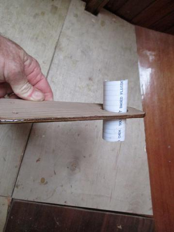
2. I needed a 1/2" fitting for the drain. this is the closest double ended male adapter I could find. But it was not what I wanted.
3. I ended up going with the brass fitting which I also did not want to use--"The lesser of two wevils."
4. The tank fits snuggly in the box and is well supported.
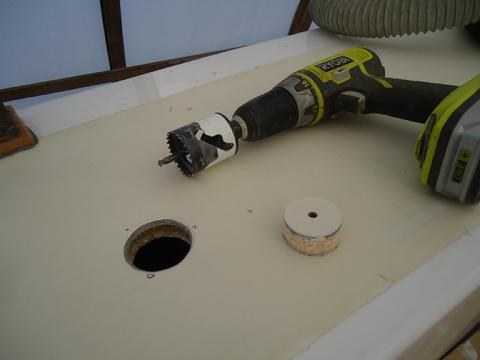
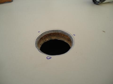
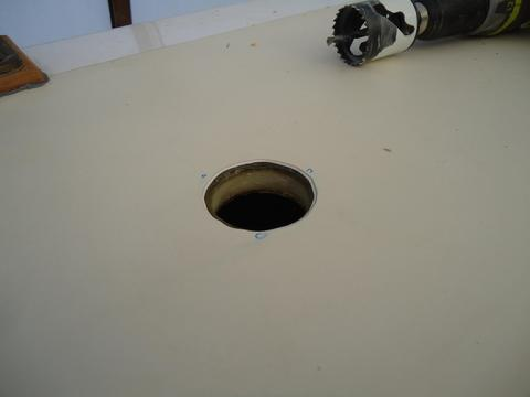
5. I drilled a 1 3/4" hole for the bronze water fill on the side deck above the fill port for the shower tank.
6. I dug the balsa core out far enough so the fasteners would not make contact with it.
7. I filled the cavity with thickened epoxy.
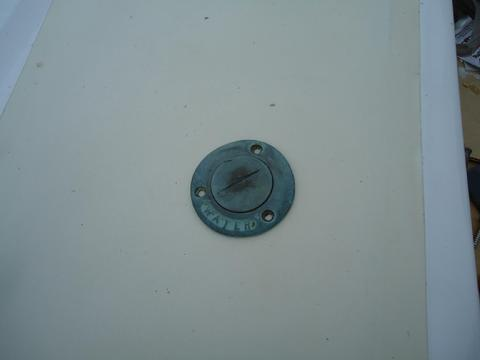
8. This is the only tank with an on deck water fill. It's one of four original fills installed on the Far Reach.
9. 1/2" ball valve plumped to threaded nipple screwed into the bottom of the tank.
I had a lot of requirements for the plumbing: simple and easy to repair; easy to remove the water tanks for cleaning and maintenance; clean tasting water; and durable. Since the water is pulled by manual pumps--one at the galley and one at the head sink--pasteurization was a not an issue. For a while I thought the solution was to use PVC pipe for the water lines. It is very durable, inexpensive, and easy to repair. But there were too many angles and it began to look like it would be a puzzle to put it together given the location of the components. I briefly thought about PEX but discarded the idea as too expensive for a non-pressurized system. I did not want to use vinyl hose because it can leave a bad taste and, because it is clear, algae can grow in it. Then, I discovered that Trident Marine makes a reinforced flexible 1/2" water hose that has a white liner in it to block light. It is only for non pressurized systems. It cost .56 cents per foot. It's very flexible. So, that is what I went with. I installed 1/2" PVC ball valves, that I bought at Lowes, to the pick up tubes on the tanks. I installed threaded 1/2" hose barbs to the ball valves. I used thick walled 1" diameter Trident Marine sanitation hose I had laying around as scrap for chaffing guards. There were three spots under the settee that would chafe the hose as it ran along side of and contacts the "knees" to which the cabin sole beams are bolted. This would be a high chafe area. To address it, I cut some 1/4" ply, drilled appropriate holes for the chaffing guards, sealed the edges with epoxy and screwed them to the knees--later I'll paint them grey. I ran the water line through these guards to prevent contact with the knees. I still need to order hose clamps but the lines are run and the installation is nearly complete.
PVC ball valves, hose barbs, and 1/2" Trident Marine water line. I still need to install the SS hose clamps.
Below:
1. This is one of the high chafe areas that had to be addressed.
2. I made a "bracket" from 1/4" ply, drilled appropriate holes, and sealed the edges with epoxy.
3. I installed the brackets with ss pan head screws.
4. I ran the water line through the chaffing guards. I'll remove the brackets and paint them with grey bilge-kote paint.
Water tank vent lins. It was time to install the vent lines for the three water tanks located in the bilge. The tanks, being positioned in the bilge, in some ways, made it more difficult than if they were under the settees. The cabin sole being right over the tank meant I needed to run the lines out to the side in order to gain vertical elevation. The risk is that water will flow into the line and form a water trap so that air can't make it's way back to the tank. Air has to flow into the tank when you pump water out or a vacuum lock will form in the tank. No air in, no water out.
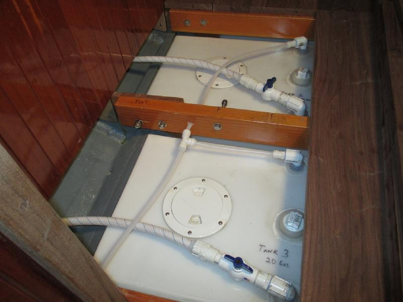
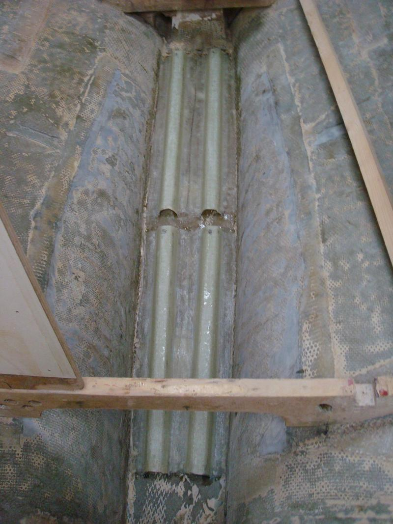
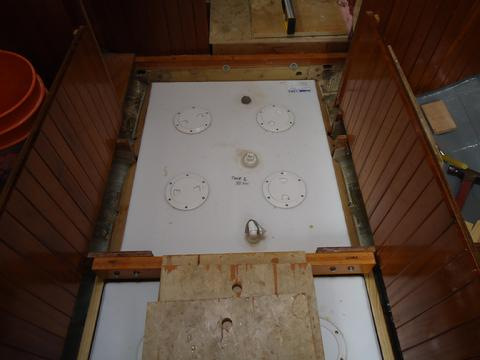
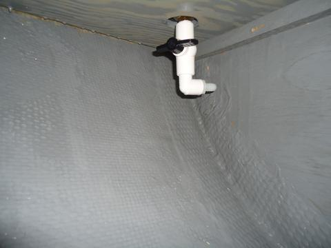
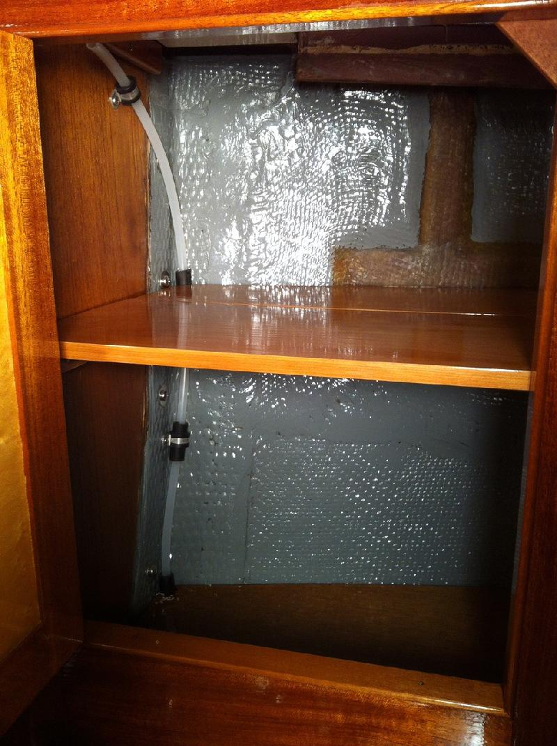
The tank vent lines are installed. I used Watts Quick Connect Fittings. I ran the line for the foward tank (not seen in this photo) foward and up behind the head sink cabinet.
I drilled a one inch diameter hole in the walnut sole under the galley sink cabinet near the center line of the boat for the aft two tanks vent line.
The best option for me, to start with, was to run one line forward from the forward most tank then angle it to the starboard side and up to the locker behind the head sink cabinet near the gunwale. For the aft two tanks I connected the vent lines together (see photo) and ran the single line up through the galley sink cabinet as it is near the centerline. That meant I did not need to run the line all the way out to the side of the tanks as I was able to route the line diagonally aft and about 10" off the center line before routing the line vertically up inside the cabinet base. The top of the vent line is about 40" above the top of the tank and because it is so close to the center of the boat theoretically the boat should be able to heel 62 degrees before water can make is way to the top of the line when the tanks are full. If the tanks are less than full we can heel even more. I think there is some risk of getting a water-block in the line with this plan. If that occurs I will run another line on the opposite side of the tanks going forward and tie in to the forward tank vent line. That way, one line will always be running up hill regardless the tack. It will not be hard to add a second line if necessary. On a lark, I decided to use the Watts Plumbing Quick Connect fittings which I have seen for a couple of years at the hardware store. I hear nothing but good things about them but I am still skeptical--I am a hose barb and SS clamp kind of guy. But, they they were easy to install and are inexpensive at about $4 each. I used a semi flexible 1/4" ID polyethylene hose that is a lot like PEX. I spent the rest of my time working on a "hold down" system to secure the tanks in place should we suffer a severe knock down. I hope to have that installed in the next couple of days.
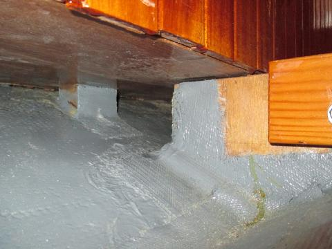
It was tim to install the water tank hold down system for the three water tanks in the bilge. After a lot of thought about what was in the art of the possible while also trying to keep it simple I decided to bolt a single wood cross member above the tanks to existing floor beams. It took a while to figure it out but it was straight forward. I glued 1/4" EPDM rubber to the bottom of the cross pieces and then through bolted them with 5/16" cap head bolts. The end pieces are half-lapped with the cross pieces. The outside edges of the tanks are held firmly in position so I don't think there is a need for more than a single, robust, cross pice above the each tank. The more difficult part was figuring out a way to hold the aft corners of the tanks in place. Eventually, I decided to cut wedge blocks from scrap Iroko (see gallery below).
The forward tank already had a floor beam installed above the tank though it cleared the top of the tank. I bolts (2) 2X8 blocks of Iroko to the beam and glued 1/4" thick EPDM rubber to the bottom of each block.
I bolted a fore-and-aft cross piece over each of the two aft tanks. The end pieces are half-lapped with the cross pieces. The cross pieces also have 1/4" EPDM rubber glued to the bottom.
I had to cut recesses in the wedge blocks to allow for the epoxy tabbing to the knees (or what would be called floors on a wood boat). It was time consuming but not difficult. I'll eventually install a simple brace to keep them from sliding out when the boat heels though they are in there snug. In reality, I am not sure how well this will work till we sail the boat. Plastic tanks have some draw backs when it comes to methods to secure them in position since there are no taps to bolt to sub framing. Custom plastic welded tanks were about 40 percent less than SS tanks. However, it has been a lot of work to develp a method for securing them in place. Would I do it again . . . ask me in a couple of years.
Below:
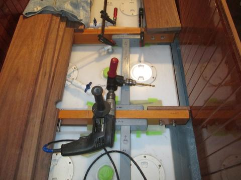
1. I tapped everthing off to prevent sawdust from falling down into the bilge. I used the right angle adapter and a standard and long bit to drill the holes.
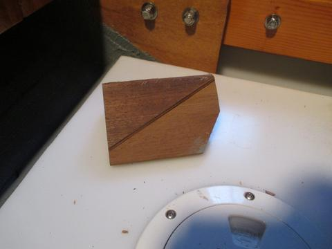
2. I used a belt sander to recess the wedge block to accomidate the fiberglass tabbing that is a little proud of the knee surface.
3. The wedge block helps keep the tank from sliding aft. The tank is also secured on the bottom, so this is additional support. The tanks are held firmly in place side to side.
4. It was trial and error to get the thickness correct. I wanted the fit snug but not so tight the wedges had to be forced into place.
5.I'll radius the inside edges after I decide on a way to hold the wedge blocks in place.
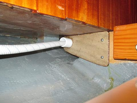
The next task was to complete the installation of the #1 (forward bilge) water tank vent line. It took a little while to determined the best way to route the line. I cut small sections of 3/8" fuel line and them slid it over the 1/4" ID vent tube as a protective sleeve. The fit was snug but with only a little effort I could easily position them where needed. I used the sleeve as a chafing guard to protect the vent line from abrasion. I used Perko aluminum and rubber hose line support clips and #8 SS 3/4" pan head self tapping screws to secure the vent tube as required. This should complete the installation of the vent lines for the three water tanks located in the bilge. We had beautiful weather today. I opened up the big doors on the SRF. It was wonderful to have some sunshine and warm temps after the month of rain, cold, and wind.
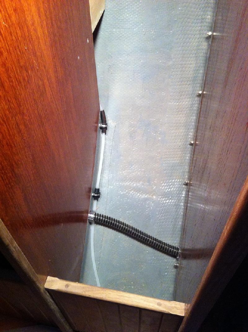
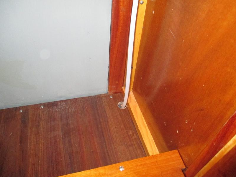
I ran the line under the sole at the aft end of the head and up through the hanging closet.
I then ran the vent line up through the outboard side of the head sink cabinet.